M3 Race Car Build (Part 3)
Our M3 race car is heading into its second season. The majority of the work was completed last year so this year the plan is to fine tune the car. Having had it on the track competing in several races the owner/driver has a good baseline for us. And one area we need to focus on this season is the aero package-- trying to find a little more speed in the corners. Time to wing it...
A quick aerodynamics primer:
We cannot alter the overall aerodynamics of the car in any appreciable amount, since that would require a wholesale reshaping of the body. Instead, we’re going to focus on creating some downforce without adding too much drag.
Why downforce? Friction. Any time a car changes velocity (when braking, accelerating or turning) the maximum force exerted by the car’s tires on the road cannot exceed the frictional force exerted by the road on the tires or else the tire (and car with it) starts to slip. We need to try to increase the force of the car on the road so that the driver can maximize the speed at which changes in velocity can occur. The most basic reaction force the car exerts on the road is its weight. Since the coefficient of friction is constant for the tire and the road one way to increase force is to increase the mass of the car. This is not a great option since increasing the weight also increases the inertia of the car when in motion, which causes a whole other set of problems. The solution is to increase aerodynamic downforce which allows the car to increase its normal reaction force without the adverse effects of increasing its mass.
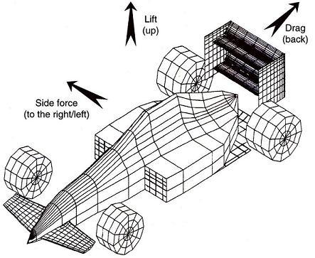
Downforce is a vertical force directed “downward” and is produced by airflow around an object such as front and rear wings, splitters and venturi tunnels. I’ll save you the mathematics behind this phenomenon; suffice to say for the race car we’re going to use a “splitter” at the front and a “wing” at the back. In order to balance the aero package, we recommend looking at both the front and rear of the car at the same time. Too much downforce at one end of the car can potentially create over or under steer.
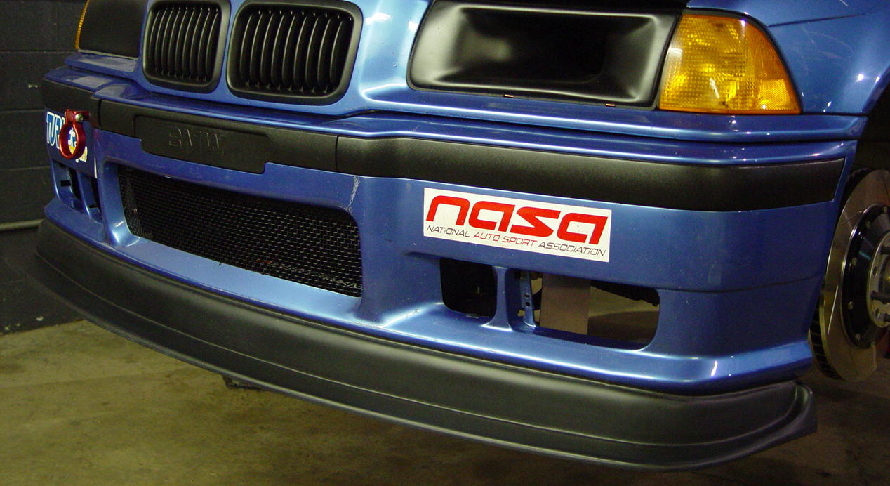
For the front we purchased a ready made splitter by MaxVelocity, their E36 M3 Evo II model. This drops the front of the car by approximately 3.5 inches and extends it 3 inches as compared to the stock piece.
The kit includes only the splitter and some rudimentary mounting equipment. To install it to our standards, we had to do quite a bit of fabricating.
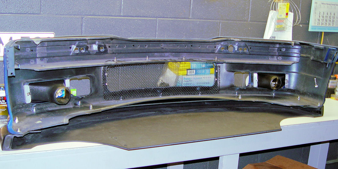
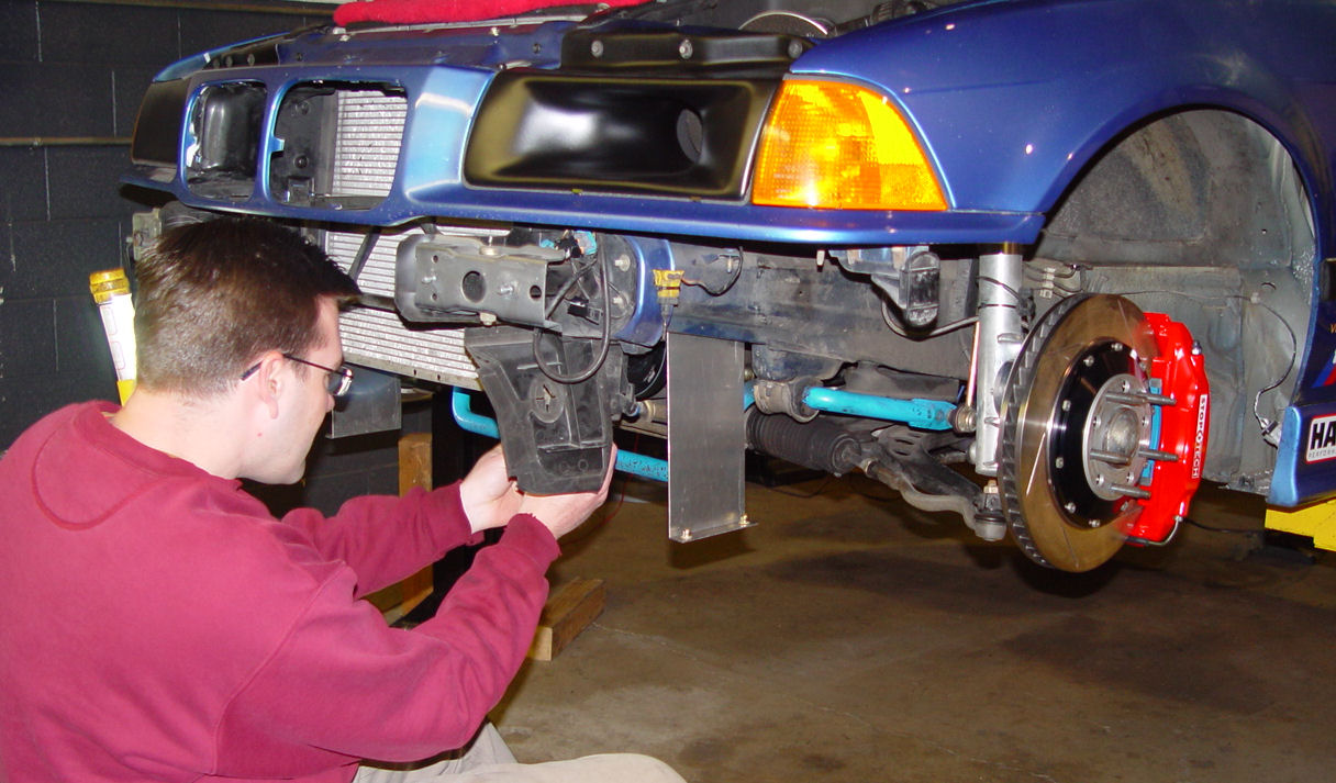
First we removed the front fascia:
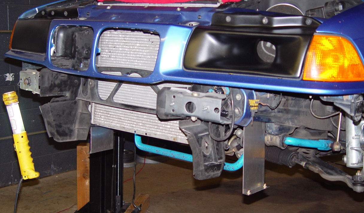
The splitter is attached to the front edge of the stock fascia using 11 nuts, bolts and oversized washers. The stock holes in the fascia were reused. We added two extra bolts near the back of the fascia, behind the OEM brake duct opening for added security. In this photo you also see the new brake duct funnels where the fog lamps used to be.
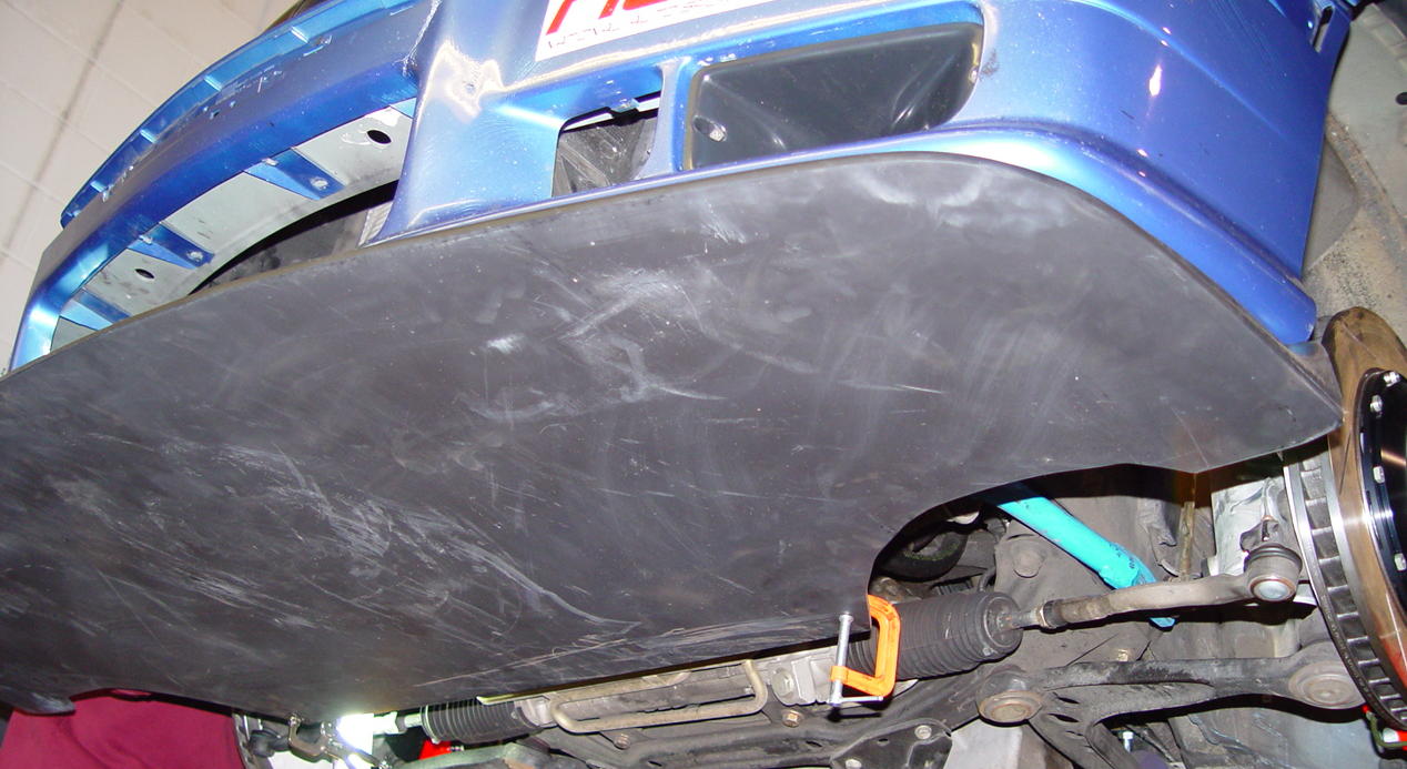
From this picture you can see that the Evo II is more than just a splitter, extending underneath the car back to the front sway bar and thereby replacing the stock belly pan.
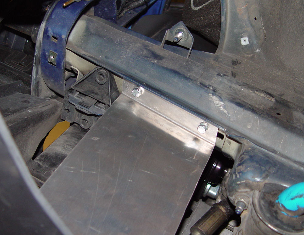
In order to properly fix the rear of the splitter/belly pan to the car we had to fabricate some mounts, or "uprights".
A closer look at the uprights installed.
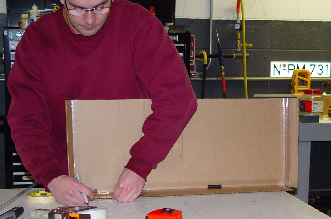
Next we had to fabricate a new diverter tray for the radiator. The stock belly pan directs air from the lower opening in the fascia up towards the radiator; the Evo II splitter had no provision for this. It is very important that the radiator continues to get fresh air. Also, allowing the air to simply pass through the opening and under the car would have created lift-- exactly the opposite of what we're trying to do with the splitter. Fabricating a custom diverter tray was no small task.
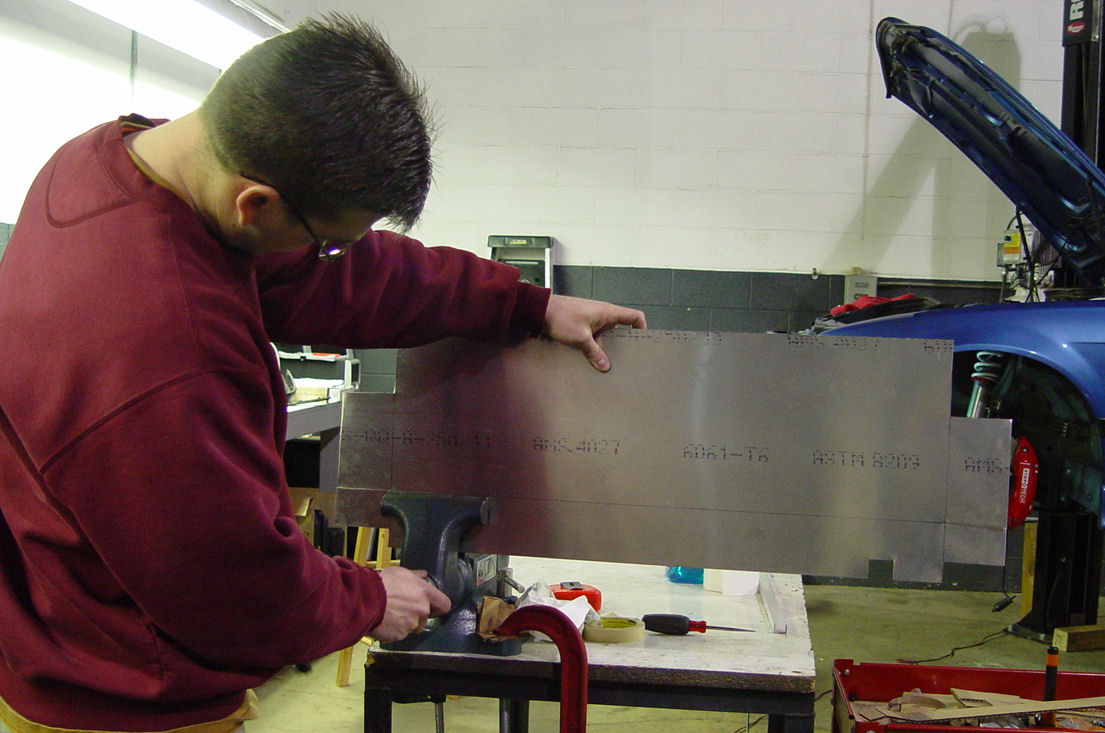
First a great many measurements were taken and a cardboard template was made.
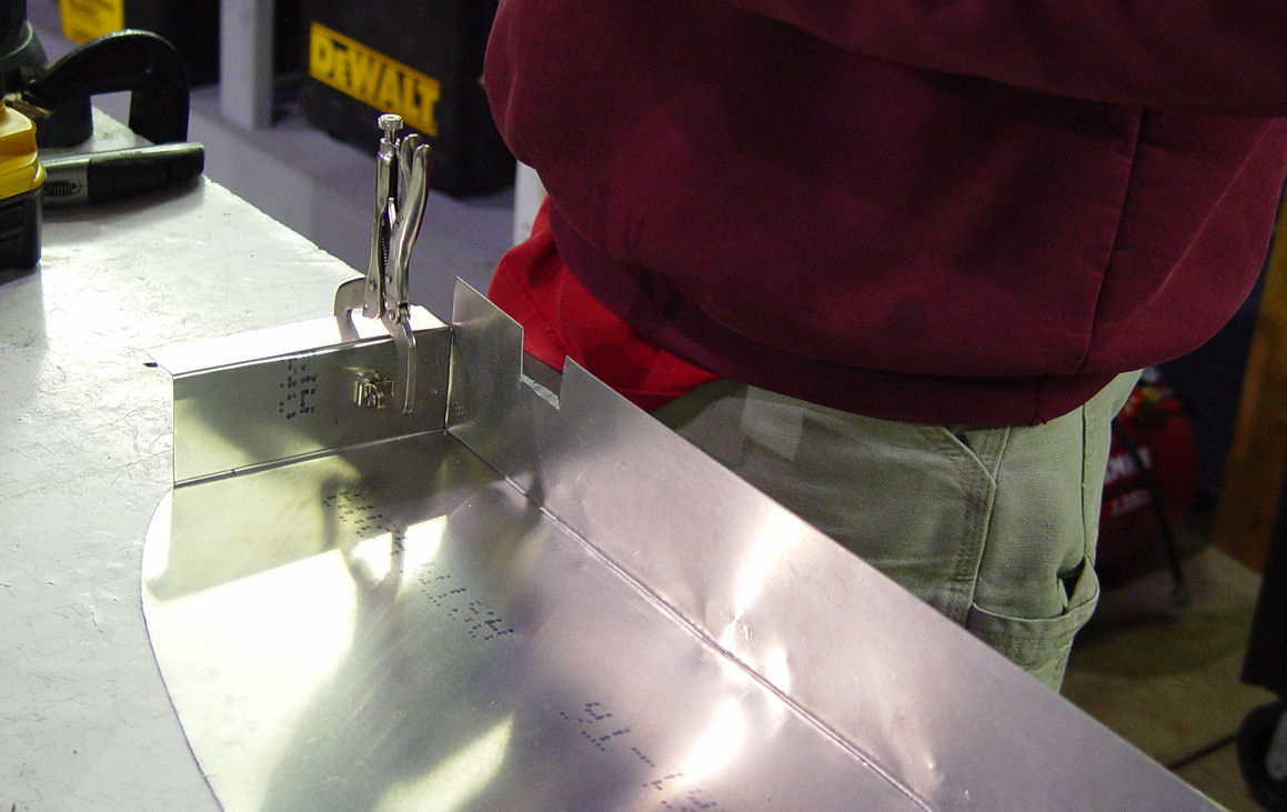
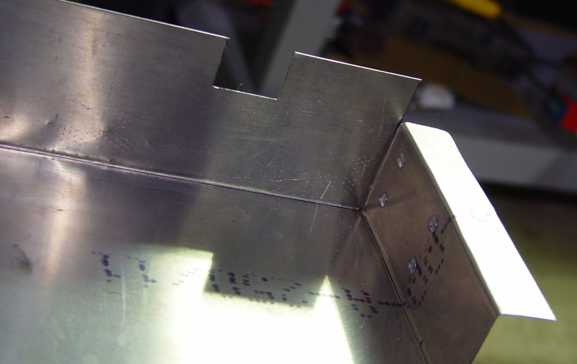
After we were certain of the design, we fabricated the tray out of strong yet lightweight aluminum stock.
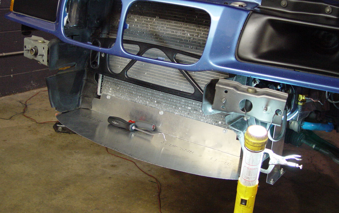
Test fit on the car.
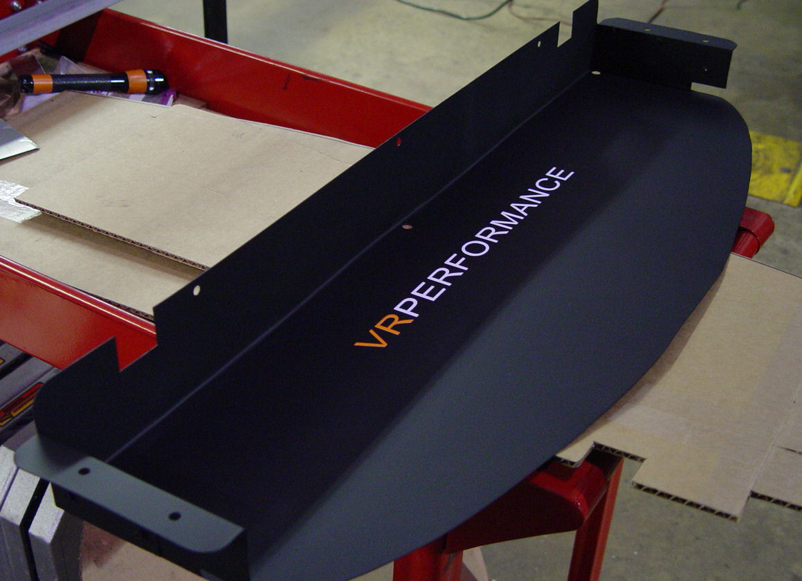
The final piece, painted and ready to be installed.

With the new diverter tray in place, the front fascia with splitter was re-installed for the final time.
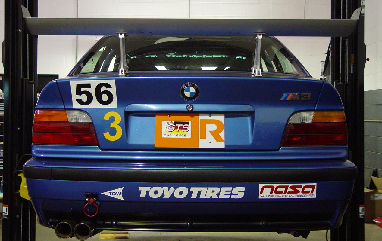
The rear wing install was much easier. We purchased a NASA approved ready made wing from APR Racing.
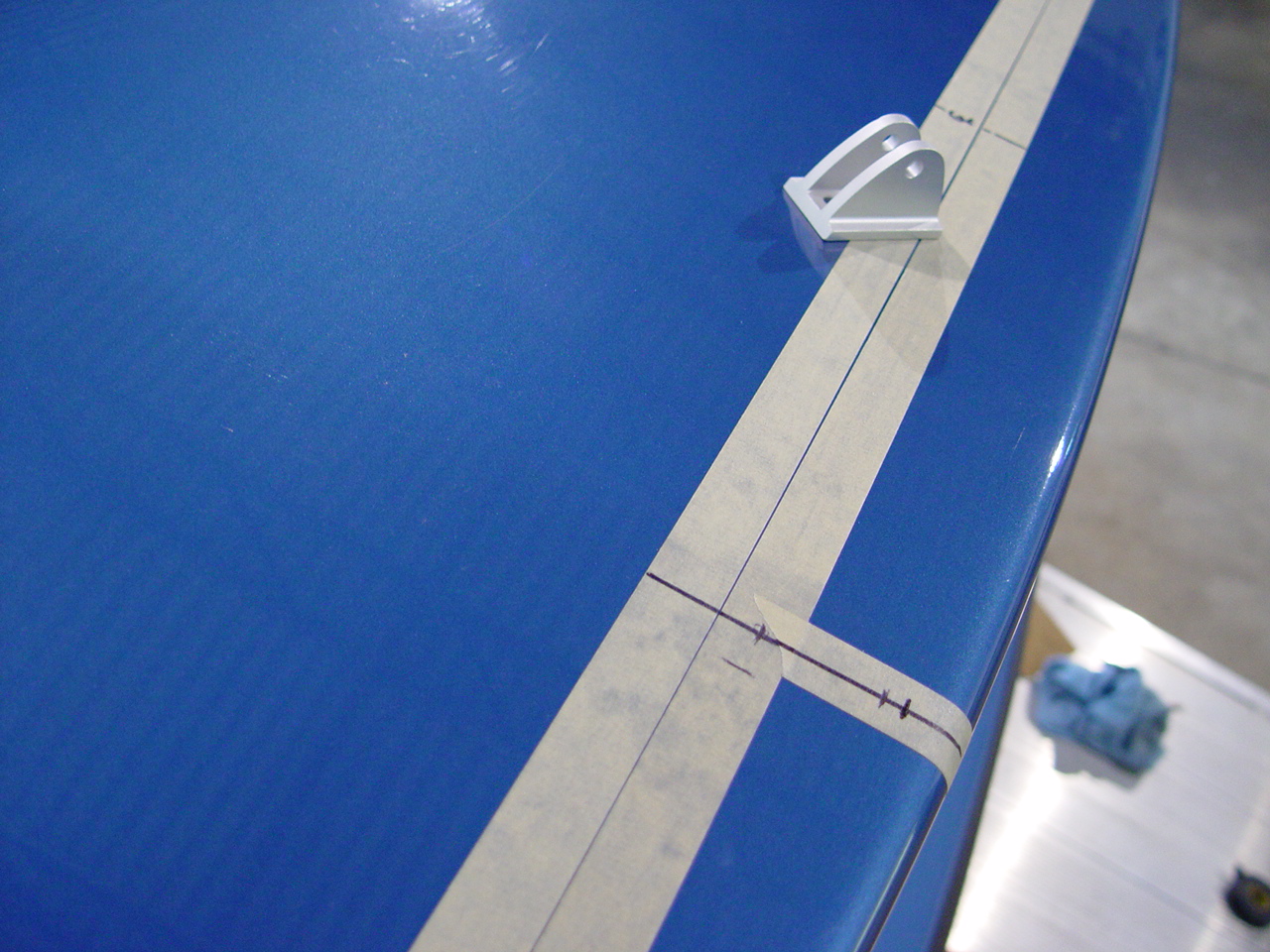
The key for this install was finding the center of the car and drilling the holes in the deck lid at the right place.
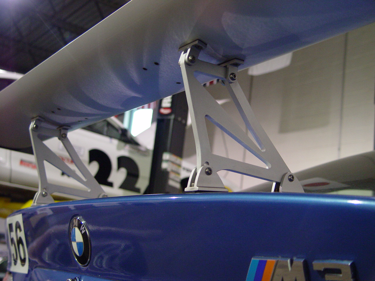
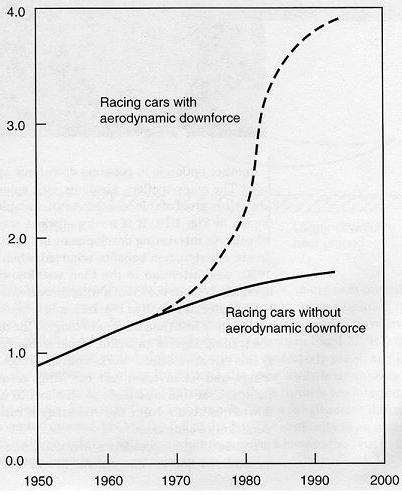
The front splitter is fixed-- in other words the amount of downforce we'll get from it cannot be changed. The rear wing is adjustable, and we'll use it to balance the car at the track. Hopefully these two aerodynamic aides will improve the cornering speeds as predicted by theory. Below is a chart showing the progress of aerodynamic aides, by decade, versus cornering speed in terms of grip (g force).